| |
|

|
|
|
|
|
|
|
|
|
|
|
|
|
|
|
|
|
|
|
|
|
|
|
|
|
|
|
|
|
|
|
|
|
|
|
|
|
| |
Wall
Thickness Calculation of Toriconical Heads Under Internal Pressure
|
|
| |
|
| |
ASME
Section VIII Div 1 paragraph UG-32
Formed Heads, and Sections, Pressure On Concave Side
|
|
|
| |
UG-32(g)
Toriconical Heads and Sections (With Transition Knuckle)
|
|
|
|
|
|
| |
|
|
|
|
|
|
|
|
|
|
|
|
|
|
|
|
|
|
|
|
|
|
|
|
|
|
|
|
|
|
|
|
|
|
| |
|
(Enter values in yellow cells for calculations)
|
|
| |
DATA INPUT
|
|
| |
|
|
|
|
|
|
|
|
|
|
|
|
|
|
|
|
|
|
|
|
|
|
|
|
|
|
|
|
|
|
|
|
|
|
|
|
|
| |
|
Design Conditions
|
|
|
Material
|
|
|
|
|
| |
|
Design Pressure, Pd =
|
|
barg
|
Toriconical
Section Material Specification (1)(2)
|
|
|
|
|
| |
|
|
|
|
|
|
|
|
|
|
|
|
|
|
|
|
|
|
|
|
|
|
|
|
|
|
|
|
|
|
|
|
|
|
|
|
|
| |
|
Design Temperature, Td =
|
|
°C
|
Allowable
Stress Toriconical Section, S =
|
|
MPa
|
|
| |
|
|
|
|
|
|
|
|
|
|
|
|
|
|
|
|
|
|
|
|
|
|
|
|
|
|
|
|
|
|
|
|
|
|
|
|
|
| |
|
Welding Efficiency, E =
|
|
|
Dimensions
|
|
|
|
|
|
|
See Table UW-12
|
|
|
Large End
Inside Diameter, D =
|
|
mm
|
|
|
|
|
|
|
Small End
Inside Diameter, d =
|
|
mm
|
|
|
|
Corrosion Allowance, CA =
|
|
mm
|
|
|
|
|
|
| |
|
|
|
|
Nominal wall
thickness before forming (6), tn =
|
|
mm
|
|
| |
|
Undertolerance Allowance (3)(4)(5), U1 =
|
|
default value = 0
|
|
|
|
|
|
|
|
|
|
|
|
|
|
|
|
|
|
|
|
|
|
|
|
|
|
|
|
|
|
|
|
|
| |
|
|
|
|
Minimum
specified thickness after forming (7), tf =
|
|
mm
|
|
| |
|
|
|
|
Minimum
required thickness Cone Section (Large End), tr =
|
|
mm
|
|
| |
|
|
|
|
|
|
|
|
|
|
|
|
|
|
|
|
|
|
|
|
|
|
|
|
|
|
|
|
|
|
|
|
|
|
|
|
|
| |
|
|
|
|
(Large End)
Inside knuckle radius (8), R =
|
|
mm
|
|
| |
|
|
|
Check inside
knuckle radius is neither less than 6% of the outside diameter of the head
skirt
|
|
|
|
|
| |
|
|
Check inside
knuckle radius of a torispherical head shall be not less than 3 times the
knuckle thickness (tk)
|
|
|
|
|
| |
|
|
|
|
|
|
|
|
|
|
|
|
|
|
|
|
|
|
|
|
|
|
|
|
|
|
|
|
|
|
|
|
|
|
|
|
|
| |
|
|
|
|
(Small End)
Inside knuckle radius (8), r =
|
|
mm
|
|
| |
|
|
|
Check inside
knuckle radius is neither less than 6% of the outside diameter of the head
skirt
|
|
|
|
|
| |
|
|
Check inside
knuckle radius of a torispherical head shall be not less than 3 times the
knuckle thickness (tk)
|
|
|
|
|
| |
|
|
|
|
|
|
|
|
|
|
|
|
|
|
|
|
|
|
|
|
|
|
|
|
|
|
|
|
|
|
|
|
|
|
|
|
|
| |
|
|
|
|
Outside
diameter of the Large End, Do =
|
|
mm
|
|
| |
|
|
|
|
Outside
diameter of the Small End, do =
|
|
mm
|
|
| |
|
|
|
|
|
|
|
|
|
|
|
|
|
|
|
|
|
|
|
|
|
|
|
|
|
|
|
|
|
|
|
|
|
|
|
|
|
| |
|
|
|
|
Length of
Conical Section, X =
|
|
mm
|
|
| |
|
|
|
|
|
|
|
|
|
|
|
|
|
|
|
|
|
|
|
|
|
|
|
|
|
|
|
|
|
|
|
|
|
|
|
|
|
| |
|
|
|
|
|
|
|
( Large End) If tr ≤ tf acceptable
|
|
|
|
|
| |
|
|
|
|
|
|
|
(Large End) If tkr ≤ tf acceptable
|
|
|
|
|
| |
|
|
|
|
|
|
|
(Small End) If tr ≤ tf acceptable
|
|
|
|
|
| |
|
|
|
|
|
|
|
(Small End) If tkr ≤ tf acceptable
|
|
|
|
|
| |
|
|
|
|
|
|
|
|
|
|
|
|
|
|
|
|
|
|
|
|
|
|
|
|
|
|
|
|
|
|
|
|
|
|
|
|
|
| |
|
Notes:
|
|
|
|
|
|
|
|
|
|
|
|
|
|
|
|
|
|
|
|
|
|
|
|
|
|
|
|
|
|
|
|
|
|
|
|
| |
(1)
|
S ≤ 66.66% of σy @ temp.
|
|
|
| |
(2)
|
S > 66.66% but < 90% of σy @ temp.
|
|
|
| |
(3)
|
As per UG-16(c)
Mill Undertolerance. Plate material shall be ordered not thinner than the
design thickness. Vessels made of plate furnished with an undertolerance of
not more than the smaller value of 0.01 in. (0.25 mm) or 6% of the ordered
thickness may be used at the full design pressure for the thickness ordered.
If the specification to which the plate is ordered allows a greater
undertolerance, the ordered thickness of the materials shall be sufficiently
greater than the design thickness so that the thickness of the material
furnished is not more than the smaller of 0.01 in. (0.25 mm) or 6% under the
design thickness.
|
|
|
| |
(4)
|
As per UG-16(d)
Pipe Undertolerance. If pipe or tube is ordered by its nominal wall
thickness, the manufacturing undertolerance on wall thickness shall be taken
into account except for nozzle wall reinforcement are a requirements in
accordance with UG-37 and UG-40. The manufacturing undertolerances are given
in the several pipe and tube specifications listed in the applicable Tables
in Subsection C. After the minimum wall thickness is determined, it shall be
increased by an amount sufficient to provide the manufacturing undertolerance
allowed in the pipe or tube specification
|
|
|
|
| |
(5)
|
If you are
ordering a head or other such fitting that is formed from plate, such as an
elliptical, torispherical head, etc, you do not need to include the
undertolerance. You do need to account for thinning during the forming of the
head. Calculations should be done based on the minimum thickness after
forming. The vendor of such heads should provide that information.
|
|
|
| |
(6)
|
It is recommended a nominal thickness before
forming 15% higher than the minimum specified thickness to ensure after
forming thickness is above it.
|
|
|
| |
(7)
|
As per UG-79
(d)(3) The reduction in weld thickness after forming shall not exceed 1/32
in. (1 mm) or 10% of the nominal thickness of the adjoining surface,
whichever is less.
|
|
|
| |
(8)
|
As per UG-32(g)
Toriconical Heads and Sections. The required thickness of the conical portion
of a toriconical head or section, in which the knuckle radius is neither less
than 6% of the outside diameter of the head skirt nor less than three times
the knuckle thickness.
|
|
|
| |
|
|
|
|
|
|
|
|
|
|
|
|
|
|
|
|
|
|
|
|
|
|
|
|
|
|
|
|
|
|
|
|
|
|
|
|
|
| |
|
|
|
|
|
|
|
|
|
|
|
|
|
|
|
|
|
|
|
|
|
|
|
|
|
|
|
|
|
|
|
|
|
|
|
|
| |
CALCULATIONS
|
|
| |
|
|
|
|
|
|
|
|
|
|
|
|
|
|
|
|
|
|
|
|
|
|
|
|
|
|
|
|
|
|
|
|
|
|
|
|
|
| |
|
Toriconical Heads
|
|
|
|
|
|
|
|
|
|
|
|
|
|
|
|
|
|
|
|
|
|
|
|
|
|
|
|
|
|
|
|
|
|
|
|
| |
|
Wall Thickness [ASME UG-32(g)]
|
|
|
|
|
|
|
|
|
|
|
|
|
|
|
|
|
|
|
|
|
|
|
|
|
|
|
|
|
|
|
|
|
|
|
|
| |
|
|
|
|
|
|
|
|
|
|
|
|
|
|
|
|
|
|
|
|
|
|
|
|
|
|
|
|
|
|
|
|
|
|
|
|
|
| |
|
Undertolerance thickness, U2 =
|
|
mm
|
U2 = tn*U1
|
|
|
|
|
|
|
|
|
|
|
|
|
|
|
|
|
|
|
|
|
|
|
|
|
|
|
|
| |
|
|
|
|
|
|
|
|
|
|
|
|
|
|
|
|
|
|
|
|
|
|
|
|
|
|
|
|
|
|
|
|
|
|
|
|
|
| |
|
Nominal thickness adjusted for corrosion and undertolerance,
nt =
|
|
mm
|
nt = tn-CA-U2
|
|
|
|
|
|
|
|
|
|
|
|
|
|
|
|
|
|
|
|
|
|
|
|
|
|
|
|
| |
|
|
|
|
|
|
|
|
|
|
|
|
|
|
|
|
|
|
|
|
|
|
|
|
|
|
|
|
|
|
|
|
|
|
|
|
|
| |
|
Large End Inside diameter with corrosion & undertolerance
removed, Dc =
|
|
mm
|
Dc = D+2CA+2U2
|
|
|
|
|
|
|
|
|
|
|
|
|
|
|
|
|
|
|
|
|
|
|
|
|
|
|
| |
|
|
|
|
|
|
|
|
|
|
|
|
|
|
|
|
|
|
|
|
|
|
|
|
|
|
|
|
|
|
|
|
|
|
|
|
|
| |
|
Small End Inside diameter with corrosion & undertolerance
removed, dc =
|
|
mm
|
dc = d+2CA+2U2
|
|
|
|
|
|
|
|
|
|
|
|
|
|
|
|
|
|
|
|
|
|
|
|
|
|
|
| |
|
|
|
|
|
|
|
|
|
|
|
|
|
|
|
|
|
|
|
|
|
|
|
|
|
|
|
|
|
|
|
|
|
|
|
|
|
| |
|
One‐half of the included (apex) angle of the cone, α ≤ 30ᵒ =
|
|
deg.
|
α =
|
arctan
|
(
|
0.5 (Dc - dc)
|
)
|
|
|
|
|
|
|
|
|
|
|
|
|
|
|
|
|
|
|
|
|
| |
|
|
|
|
X
|
|
|
|
|
|
|
|
|
|
|
|
|
|
|
|
|
|
|
|
|
| |
|
|
|
|
|
|
|
|
|
|
|
|
|
|
|
|
|
|
|
|
|
|
|
|
|
|
|
|
|
|
|
|
|
|
|
|
|
| |
|
(Large End) Inside knuckle radius with corrosion &
undertolerance removed,Rc =
|
|
mm
|
Rc = R+CA+U2
|
|
|
|
|
|
|
|
|
|
|
|
|
|
|
|
|
|
|
|
|
|
|
|
|
|
|
|
| |
|
|
|
|
|
|
|
|
|
|
|
|
|
|
|
|
|
|
|
|
|
|
|
|
|
|
|
|
|
|
|
|
|
|
|
|
|
| |
|
(Small End) Inside knuckle radius with corrosion &
undertolerance removed, rc =
|
|
mm
|
rc = r+CA+U2
|
|
|
|
|
|
|
|
|
|
|
|
|
|
|
|
|
|
|
|
|
|
|
|
|
|
|
|
| |
|
|
|
|
|
|
|
|
|
|
|
|
|
|
|
|
|
|
|
|
|
|
|
|
|
|
|
|
|
|
|
|
|
|
|
|
|
| |
|
(Large End) ID of the conical portion with corrosion &
undertolerance removed, Di =
|
|
mm
|
Di = Dc−2Rc(1−cos α)
|
|
|
|
|
|
|
|
|
|
|
|
|
|
|
|
|
|
|
|
|
|
|
|
|
| |
|
|
|
|
|
|
|
|
|
|
|
|
|
|
|
|
|
|
|
|
|
|
|
|
|
|
|
|
|
|
|
|
|
|
|
|
|
| |
|
(Small End) ID of the conical portion with corrosion &
undertolerance removed, di =
|
|
mm
|
di = dc−2rc(1−cos α)
|
|
|
|
|
|
|
|
|
|
|
|
|
|
|
|
|
|
|
|
|
|
|
|
|
| |
|
|
|
|
|
|
|
|
|
|
|
|
|
|
|
|
|
|
|
|
|
|
|
|
|
|
|
|
|
|
|
|
|
|
|
|
|
| |
|
Minimum required thickness (Large End), t =
|
|
mm
|
t =
|
P Di
|
|
|
|
|
|
|
|
|
|
|
|
|
|
|
|
|
|
|
|
|
| |
|
|
|
|
2 cos α (S E − 0.6
P)
|
|
|
|
|
|
|
|
|
|
|
|
|
|
|
|
|
|
|
|
|
| |
|
|
|
|
|
|
|
|
|
|
|
|
|
|
|
|
|
|
|
|
|
|
|
|
|
|
|
|
|
|
|
|
|
|
|
|
|
| |
|
Minimum required thickness (Large End), tr =
|
|
mm
|
tr =
|
P Di
|
+ CA
|
|
|
|
|
|
|
|
|
|
|
|
|
|
|
|
|
|
| |
|
|
|
|
2 cos α (S E − 0.6
P)
|
|
|
|
|
|
|
|
|
|
|
|
|
|
|
|
|
|
| |
|
Minimum specified thickness after forming, tf =
|
|
mm
|
|
|
|
|
|
|
|
|
|
|
|
|
|
|
|
|
|
|
|
|
|
|
|
|
|
|
|
|
|
|
|
|
|
| |
|
|
|
|
|
|
|
|
|
|
|
|
|
|
|
|
|
|
|
|
|
|
|
|
|
|
|
|
|
|
|
|
|
|
|
|
|
|
| |
|
Check If tr ≤ tf (Large End)
|
|
|
|
|
|
|
|
|
|
|
|
|
|
|
|
|
|
|
|
|
|
|
|
|
|
|
|
|
|
|
|
|
|
|
|
| |
|
|
|
|
|
|
|
|
|
|
|
|
|
|
|
|
|
|
|
|
|
|
|
|
|
|
|
|
|
|
|
|
|
|
|
|
|
| |
|
Minimum required thickness (Small End), t =
|
|
mm
|
t =
|
P di
|
|
|
|
|
|
|
|
|
|
|
|
|
|
|
|
|
|
|
|
|
| |
|
|
|
|
2 cos α (S E − 0.6
P)
|
|
|
|
|
|
|
|
|
|
|
|
|
|
|
|
|
|
|
|
|
| |
|
|
|
|
|
|
|
|
|
|
|
|
|
|
|
|
|
|
|
|
|
|
|
|
|
|
|
|
|
|
|
|
|
|
|
|
|
| |
|
Minimum required thickness (Small End), tr =
|
|
mm
|
tr =
|
P di
|
+ CA
|
|
|
|
|
|
|
|
|
|
|
|
|
|
|
|
|
|
| |
|
|
|
|
2 cos α (S E − 0.6
P)
|
|
|
|
|
|
|
|
|
|
|
|
|
|
|
|
|
|
| |
|
Minimum specified thickness after forming, tf =
|
|
mm
|
|
|
|
|
|
|
|
|
|
|
|
|
|
|
|
|
|
|
|
|
|
|
|
|
|
|
|
|
|
|
|
|
|
| |
|
|
|
|
|
|
|
|
|
|
|
|
|
|
|
|
|
|
|
|
|
|
|
|
|
|
|
|
|
|
|
|
|
|
|
|
|
|
| |
|
Check If tr ≤ tf (Small End)
|
|
|
|
|
|
|
|
|
|
|
|
|
|
|
|
|
|
|
|
|
|
|
|
|
|
|
|
|
|
|
|
|
|
|
|
| |
|
|
|
|
|
|
|
|
|
|
|
|
|
|
|
|
|
|
|
|
|
|
|
|
|
|
|
|
|
|
|
|
|
|
|
|
|
| |
|
Knuckle Thickness [ASME UG-32(g) & App 1-4(d)]
|
|
|
|
|
|
|
|
|
|
|
|
|
|
|
|
|
|
|
|
|
|
|
|
|
|
|
|
|
|
|
|
|
|
|
|
| |
|
|
|
|
|
|
|
|
|
|
|
|
|
|
|
|
|
|
|
|
|
|
|
|
|
|
|
|
|
|
|
|
|
|
|
|
|
| |
|
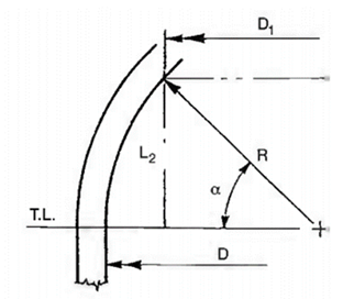
Inside spherical or crown radius (Large End), LL (9) =
|
|
mm
|
LL =
|
Di
|
|
|
|
|
|
|
|
|
|
|
|
|
|
|
|
|
|
|
|
|
|
|
|
|
|
|
|
| |
|
|
|
|
2 x cos α
|
|
|
|
|
|
|
|
|
|
|
|
|
|
|
|
|
|
|
|
|
|
|
|
|
|
|
|
| |
|
|
|
|
|
|
|
|
|
|
|
|
|
|
|
|
|
|
|
|
|
|
|
|
|
|
|
|
|
|
|
|
|
|
|
|
|
| |
|
Factor depending on the head proportion (Large End) L/rc, ML =
|
|
|
ML =
|
1
|
(
|
3 + (L/Rc)1/2
|
)
|
|
|
|
|
|
|
|
|
|
|
|
|
|
|
|
|
|
|
|
|
|
|
| |
|
|
|
|
4
|
|
|
|
|
|
|
|
|
|
|
|
|
|
|
|
|
|
|
|
|
|
|
| |
|
|
|
|
|
|
|
|
|
|
|
|
|
|
|
|
|
|
|
|
|
|
|
|
|
|
|
|
|
|
|
|
|
|
|
|
|
| |
|
Minimum required knuckle thickness (Large End), tk =
|
|
mm
|
tk =
|
P LL ML
|
|
|
|
|
|
|
|
|
|
|
|
|
|
|
|
|
|
|
|
|
|
|
|
|
|
| |
|
|
|
|
2 S E − 0.2 P
|
|
|
|
|
|
|
|
|
|
|
|
|
|
|
|
|
|
|
|
|
|
|
|
|
|
| |
|
|
|
|
|
|
|
|
|
|
|
|
|
|
|
|
|
|
|
|
|
|
|
|
|
|
|
|
|
|
|
|
|
|
|
|
|
| |
|
Minimum required knuckle thickness (Large End), tkr =
|
|
mm
|
tkr =
|
P LL ML
|
+ CA
|
|
|
|
|
|
|
|
|
|
|
|
|
|
|
|
|
|
|
|
|
|
| |
|
|
|
|
2 S E − 0.2 P
|
|
|
|
|
|
|
|
|
|
|
|
|
|
|
|
|
|
|
|
|
|
| |
|
Check If tkr ≤ tf (Large End)
|
|
|
|
|
|
|
|
|
|
|
|
|
|
|
|
|
|
|
|
|
|
|
|
|
|
|
|
|
|
|
|
|
|
|
|
| |
|
|
|
|
|
|
|
|
|
|
|
|
|
|
|
|
|
|
|
|
|
|
|
|
|
|
|
|
|
|
|
|
|
|
|
|
|
| |
|
Inside spherical or crown radius (Small End), Ls (9) =
|
|
mm
|
Ls =
|
di
|
|
|
|
|
|
|
|
|
|
|
|
|
|
|
|
|
|
|
|
|
|
|
|
|
|
|
|
| |
|
|
|
|
2 x cos α
|
|
|
|
|
|
|
|
|
|
|
|
|
|
|
|
|
|
|
|
|
|
|
|
|
|
|
|
| |
|
|
|
|
|
|
|
|
|
|
|
|
|
|
|
|
|
|
|
|
|
|
|
|
|
|
|
|
|
|
|
|
|
|
|
|
|
| |
|
Factor depending on the head proportion (Small End) L/rc, Ms =
|
|
|
Ms =
|
1
|
(
|
3 + (L/rc)1/2
|
)
|
|
|
|
|
|
|
|
|
|
|
|
|
|
|
|
|
|
|
|
|
|
|
| |
|
|
|
|
4
|
|
|
|
|
|
|
|
|
|
|
|
|
|
|
|
|
|
|
|
|
|
|
| |
|
|
|
|
|
|
|
|
|
|
|
|
|
|
|
|
|
|
|
|
|
|
|
|
|
|
|
|
|
|
|
|
|
|
|
|
|
| |
|
Minimum required knuckle thickness (Small End), tk =
|
|
mm
|
tk =
|
P Ls Ms
|
|
|
|
|
|
|
|
|
|
|
|
|
|
|
|
|
|
|
|
|
|
|
|
|
|
| |
|
|
|
|
2 S E − 0.2 P
|
|
|
|
|
|
|
|
|
|
|
|
|
|
|
|
|
|
|
|
|
|
|
|
|
|
| |
|
|
|
|
|
|
|
|
|
|
|
|
|
|
|
|
|
|
|
|
|
|
|
|
|
|
|
|
|
|
|
|
|
|
|
|
|
| |
|
Minimum required knuckle thickness (Small End), tkr =
|
|
mm
|
tkr =
|
P Ls Ms
|
+ CA
|
|
|
|
|
|
|
|
|
|
|
|
|
|
|
|
|
|
|
|
|
|
| |
|
|
|
|
2 S E − 0.2 P
|
|
|
|
|
|
|
|
|
|
|
|
|
|
|
|
|
|
|
|
|
|
| |
|
Check If tkr ≤ tf (Small End)
|
|
|
|
|
|
|
|
|
|
|
|
|
|
|
|
|
|
|
|
|
|
|
|
|
|
|
|
|
|
|
|
|
|
|
|
| |
|
|
|
|
|
|
|
|
|
|
|
|
|
|
|
|
|
|
|
|
|
|
|
|
|
|
|
|
|
|
|
|
|
|
|
|
|
| |
|
Maximum allowable working pressure Cone Section [ASME
UG-32(g)
|
|
|
|
|
|
|
|
|
|
|
|
|
|
|
|
|
|
|
|
|
|
|
|
|
|
|
|
|
|
|
|
|
|
|
|
| |
|
Maximum allowable working pressure for Toriconical Head, MAWPC =
|
|
barg
|
MAWPC
=
|
2 S E nt cos α
|
|
|
|
|
|
|
|
|
|
|
|
|
|
|
|
|
|
|
|
|
| |
|
|
|
|
Di + 1.2 nt cos α
|
|
|
|
|
|
|
|
|
|
|
|
|
|
|
|
|
|
|
|
|
| |
|
Maximum allowable working pressure Knuckle [ASME App 1-4(d)]
|
|
|
|
|
|
|
|
|
|
|
|
|
|
|
|
|
|
|
|
|
|
|
|
|
|
|
|
|
|
|
|
|
|
|
|
| |
|
Maximum allowable working pressure for Knuckle, MAWPK =
|
|
barg
|
MAWPK
=
|
2 S E nt
|
|
|
|
|
|
|
|
|
|
|
|
|
|
|
|
|
|
|
|
|
|
|
| |
|
|
|
|
LL ML + 0.2 nt
|
|
|
|
|
|
|
|
|
|
|
|
|
|
|
|
|
|
|
|
|
|
|
| |
|
|
|
|
|
|
|
|
|
|
|
|
|
|
|
|
|
|
|
|
|
|
|
|
|
|
|
|
|
|
|
|
|
|
|
|
|
| |
|
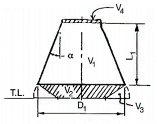
Volume & Weight Calculation
|
|
|
|
|
|
|
|
|
|
|
|
|
|
|
|
|
|
|
|
|
|
|
|
|
|
|
|
|
|
|
|
|
|
|
|
| |
|
Inside Volume
|
|
|
|
|
|
|
|
|
|
|
|
|
|
|
|
|
|
|
|
|
|
|
|
|
|
|
|
|
|
|
|
|
|
|
|
| |
|
Large End Inside diameter, D =
|
|
mm
|
|
|
|
|
|
|
|
|
|
|
|
|
|
|
|
|
|
| |
|
Small End Inside diameter, d =
|
|
mm
|
|
|
|
|
|
|
|
|
|
|
|
|
|
|
|
|
| |
|
(Large End) Inside knuckle radius, R =
|
|
mm
|
|
|
|
|
|
|
|
|
|
|
|
|
|
|
|
|
| |
|
(Small End) Inside knuckle radius, r =
|
|
mm
|
|
|
|
|
|
|
|
|
|
|
|
|
|
|
|
|
| |
|
α =
|
|
deg.
|
|
|
|
|
|
|
|
|
|
|
|
|
|
|
|
|
| |
|
X =
|
|
mm
|
|
|
|
|
|
|
|
|
|
|
|
|
|
|
|
|
| |
|
L2
= R * sin(α) =
|
|
mm
|
|
|
|
|
|
|
|
|
|
|
|
|
|
|
|
|
| |
|
L3
= r * Tan(α/2) =
|
|
mm
|
|
|
|
|
|
|
|
|
|
|
|
|
|
|
|
|
| |
|
L1
= X - L2 -
L3 =
|
|
mm
|
|
|
|
|
|
|
|
|
|
|
|
|
|
|
|
|
| |
|
ID of the conical portion, D1 = D – 2R(1 – cos α) =
|
|
mm
|
|
|
|
|
|
|
|
|
|
|
|
|
|
|
|
|
| |
|
D2
= D - 2R =
|
|
mm
|
|
|
|
|
|
|
|
|
|
|
|
|
|
|
|
|
| |
|
|
|
|
|
|
|
|
|
|
|
|
|
|
|
|
|
|
|
|
|
| |
|
Outside Volume
|
|
|
|
|
|
|
|
|
|
|
|
|
|
|
|
|
|
|
| |
|
Outside diameter of the Large End, Do =
|
|
mm
|
|
|
|
|
|
|
|
|
|
|
|
|
|
|
|
|
| |
|
Outside diameter of the head Small End, do =
|
|
mm
|
|
|
|
|
|
|
|
|
|
|
|
|
|
|
|
|
| |
|
(Large End) Outside knuckle radius, Ro =
|
|
mm
|
|
|
|
|
|
|
|
|
|
|
|
|
|
|
|
|
| |
|
(Small End) Outside knuckle radius, ro =
|
|
mm
|
|
|
|
|
|
|
|
|
|
|
|
|
|
|
|
|
| |
|
α =
|
|
deg.
|
|
|
|
|
|
|
|
|
|
|
|
|
|
|
|
|
| |
|
X =
|
|
mm
|
|
|
|
|
|
|
|
|
|
|
|
|
|
|
|
|
| |
|
L2
= Ro *
sin(α) =
|
|
mm
|
|
|
|
|
|
|
|
|
|
|
|
|
|
|
|
|
| |
|
L3
= ro *
Tan(α/2) =
|
|
mm
|
|
|
|
|
|
|
|
|
|
|
|
|
|
|
|
|
| |
|
L1
= X - L2 -
L3 =
|
|
mm
|
|
|
|
|
|
|
|
|
|
|
|
|
|
|
|
|
|
|
|
|
|
|
|
|
|
|
|
|
|
|
|
|
|
| |
|
OD of the conical portion, D1 = Do – 2Ro(1 – cos α) =
|
|
mm
|
|
|
|
|
|
|
|
|
|
|
|
|
|
|
|
|
|
|
|
|
|
|
|
|
|
|
|
|
|
|
|
|
|
| |
|
D2
= Do -
2Ro=
|
|
mm
|
|
|
|
|
|
|
|
|
|
|
|
|
|
|
|
|
|
|
|
|
|
|
|
|
|
|
|
|
|
|
|
|
|
| |
|
|
|
|
|
|
|
|
|
|
|
|
|
|
|
|
|
|
|
|
|
|
|
|
|
|
|
|
|
|
|
|
|
|
|
|
|
| |
|
|
|
|
|
|
|
|
|
|
|
|
|
|
|
|
|
|
|
|
|
|
|
|
|
|
|
|
|
|
|
|
|
|
|
|
|
| |
|
Inside Volume
|
|
|
|
|
|
|
|
|
|
|
|
|
|
|
|
|
|
|
|
|
|
|
|
|
|
|
|
|
|
|
|
|
|
|
|
| |
|
V1
=
|
|
m³
|
V1 =
|
(
|
πL1(D12 + D1d + d2)
|
)
|
/
109
|
|
|
|
|
|
|
|
|
|
|
|
|
|
|
|
|
| |
|
|
|
|
12
|
|
|
|
|
|
|
|
|
|
|
|
|
|
|
|
|
|
|
|
|
|
|
|
|
|
|
|
|
|
|
|
|
|
|
|
|
|
|
|
|
|
|
|
|
|
|
|
|
|
|
|
|
|
|
| |
|
V2
=
|
|
m³
|
V2 =
|
(
|
πL2(D12 + D1D2 + D22)
|
)
|
/ 109
|
|
|
|
|
|
|
|
|
|
|
|
|
|
|
| |
|
|
|
|
12
|
|
|
|
|
|
|
|
|
|
|
|
|
|
|
|
|
|
|
|
|
|
|
|
|
|
|
|
|
|
|
|
|
|
|
|
|
|
|
|
|
|
|
|
|
|
|
|
|
|
|
|
|
| |
|
V3
=
|
|
m³
|
V3 =
|
(
|
120 R3 π sin(α/2)
cos(α/2) + 0.25 D2 R2 (α/2)
|
)
|
/ 109
|
|
|
|
|
|
| |
|
|
|
|
90
|
|
|
|
|
|
|
|
|
|
|
|
|
|
|
|
|
|
|
|
|
|
|
|
|
|
|
|
|
|
|
|
|
|
|
|
|
|
|
|
|
|
|
|
| |
|
V4
=
|
|
m³
|
V4 =
|
(
|
πd2L3
|
)
|
/ 109
|
|
|
|
|
|
|
|
|
|
|
|
|
|
|
|
|
|
|
|
|
|
| |
|
|
|
|
4
|
|
|
|
|
|
|
|
|
|
|
|
|
|
|
|
|
|
|
|
|
|
|
|
|
|
|
|
|
|
|
|
|
|
|
|
|
|
|
|
|
|
|
|
|
|
|
|
|
|
|
|
|
|
|
|
|
|
|
|
| |
|
Vi =
|
|
m³
|
Vi =
|
V1 + V2 + V3 + V4
|
|
|
|
|
|
|
|
|
|
|
|
|
|
|
|
|
|
|
|
|
|
| |
|
|
|
|
|
|
|
|
|
|
|
|
|
|
|
|
|
|
|
|
|
|
|
|
|
|
|
|
|
|
|
|
|
|
|
|
|
| |
|
Outside Volume
|
|
|
|
|
|
|
|
|
|
|
|
|
|
|
|
|
|
|
|
|
|
|
|
|
|
|
|
|
|
|
|
|
|
|
|
| |
|
V1
=
|
|
m³
|
V1 =
|
(
|
πL1(D12 + D1do + do2)
|
)
|
/
109
|
|
|
|
|
|
|
|
|
|
|
|
|
|
|
|
|
| |
|
|
|
|
12
|
|
|
|
|
|
|
|
|
|
|
|
|
|
|
|
|
|
|
|
|
|
|
|
|
|
|
|
|
|
|
|
|
|
|
|
|
|
|
|
|
|
|
|
|
|
|
|
|
|
|
|
|
|
|
| |
|
V2
=
|
|
m³
|
V2 =
|
(
|
πL2(D12 + D1D2 + D22)
|
)
|
/ 109
|
|
|
|
|
|
|
|
|
|
|
|
|
|
|
| |
|
|
|
|
12
|
|
|
|
|
|
|
|
|
|
|
|
|
|
|
|
|
|
|
|
|
|
|
|
|
|
|
|
|
|
|
|
|
|
|
|
|
|
|
|
|
|
|
|
|
|
|
|
|
|
|
|
|
| |
|
V3
=
|
|
m³
|
V3 =
|
(
|
120 Ro3 π sin(α/2) cos(α/2) + 0.25 D2 Ro2 (α/2)
|
)
|
/ 109
|
|
|
|
|
|
| |
|
|
|
|
90
|
|
|
|
|
|
|
|
|
|
|
|
|
|
|
|
|
|
|
|
|
|
|
|
|
|
|
|
|
|
|
|
|
|
|
|
|
|
|
|
|
|
|
|
| |
|
V4
=
|
|
m³
|
V4 =
|
(
|
πdo2L3
|
)
|
/ 109
|
|
|
|
|
|
|
|
|
|
|
|
|
|
|
|
|
|
|
|
|
|
| |
|
|
|
|
4
|
|
|
|
|
|
|
|
|
|
|
|
|
|
|
|
|
|
|
|
|
|
|
|
|
|
|
|
|
|
|
|
|
|
|
|
|
|
|
|
|
|
|
|
|
|
|
|
|
|
|
|
|
|
|
|
|
|
|
|
| |
|
Vo =
|
|
m³
|
Vo =
|
V1 + V2 + V3 + V4
|
|
|
|
|
|
|
|
|
|
|
|
|
|
|
|
|
|
|
|
|
|
| |
|
|
|
|
|
|
|
|
|
|
|
|
|
|
|
|
|
|
|
|
|
|
|
|
|
|
|
|
|
|
|
|
|
|
|
|
|
| |
|
|
|
|
|
|
|
|
|
|
|
|
|
|
|
|
|
|
|
|
|
|
|
|
|
|
|
|
|
|
|
|
|
|
|
|
|
| |
|
Weight =
|
|
Kg
|
W =
|
(Vo - Vi) ρm
|
|
|
|
|
|
|
|
|
|
|
|
|
|
|
|
|
|
|
|
|
|
|
|
|
| |
|
|
|
|
|
|
|
|
|
|
|
|
|
|
|
|
|
|
|
|
|
|
|
|
|
|
|
|
|
|
|
|
|
|
|
|
|
| |
|
Note:
|
|
|
|
|
|
|
|
|
|
|
|
|
|
|
|
|
|
|
|
|
|
|
|
|
|
|
|
|
|
|
|
|
|
|
|
| |
(9)
|
As per UG-32(i)
The inside crown radius to which an unstayed head is dished shall be not
greater than the outside diameter of the skirt of the head.
|
|
|
| |
|
|
|
|
|
|
|
|
|
|
|
|
|
|
|
|
|
|
|
|
|
|
|
|
|
|
|
|
|
|
|
|
|
|
|
|
|
| |
|
|
|
|
|
|
|
|
|
|
|
|
|
|
|
|
|
|
|
|
|
|
|
|
|
|
|
|
|
|
|
|
|
|
| |
RESULT
|
|
|
|
|
|
|
|
|
|
|
|
|
|
|
|
|
|
|
|
|
|
|
|
|
|
|
|
|
|
|
|
|
|
|
|
|
|
|
|
| |
|
Design Conditions
|
|
|
|
|
|
|
|
|
|
|
|
|
Design Pressure, Pd =
|
|
barg
|
|
|
|
|
|
|
|
|
|
Design Temperature, Td =
|
|
°C
|
|
|
|
|
|
|
|
|
|
|
|
|
|
|
|
|
|
|
|
| |
|
Material
|
|
|
|
|
|
|
|
|
|
|
|
Toricónical Head Material
|
|
|
|
|
|
|
|
|
|
|
|
|
|
|
|
|
|
|
|
|
|
| |
|
Dimensions
|
|
|
|
|
|
|
|
|
|
|
|
Large End Inside Diameter, D =
|
|
mm
|
|
|
|
|
|
|
|
|
|
Small End Inside Diameter, d =
|
|
mm
|
|
|
|
|
|
|
|
|
|
Minimum specified thickness after forming, tf =
|
|
mm
|
|
|
|
|
|
|
|
|
|
Length of Toriconical Head, X =
|
|
mm
|
|
|
|
|
|
|
|
|
|
|
|
|
|
|
|
|
|
|
|
| |
|
Maximum allowable working pressure, MAWPC =
|
|
barg
|
|
|
|
|
|
|
|
| |
|
Maximum allowable working pressure, MAWPK =
|
|
barg
|
|
|
|
|
|
|
|
|
|
Inside Volume =
|
|
m³
|
|
|
|
|
|
|
|
|
|
Outside Volume =
|
|
m³
|
|
|
|
|
|
|
|
|
|
Weight =
|
|
Kg
|
|
|
|
|
|
|
|
|
|
|
|
|
|
|
|
|
|
|
|
|
|
|
|
|
|
|
|
|
|
|
|
|
|
|
|
|
|
|
|
|
|
|
|
|
|
|
|
|
|
|
|
|
|
|
|
|
|
|
|
|
|
|
|
|
|
|
|
|
|
|
|
|
|
|
|
|
|
|
|
|
|
|
|
|
|
|
|
|
|
|
|
|
|
|
|
|
|
|
|
|
|
|
|
|
|
|
|
|
|
|
|
|
|
|
|
|
|
|
|
|
|
|
|
|
|
|
|
|
|
|
|
|
|
| |
|
|
|
|
|
|
|
|
|
|
|
|
|
|
|
|
|
|
|
|
|
|
|
|
|
|
|
|
|
|
|
|
|
|
|
|
|